Alessandro Arduino1, Umberto Zanovello1, Jeff Hand2, Luca Zilberti1, Rüdiger Brühl3, Mario Chiampi1, and Oriano Bottauscio1
1Istituto Nazionale di Ricerca Metrologica, Torino, Italy, 2School of Biomedical Engineering and Imaging Sciences, King’s College London, London, United Kingdom, 3Physikalisch-Technische Bundesanstalt, Braunschweig and Berlin, Germany
1Istituto Nazionale di Ricerca Metrologica, Torino, Italy, 2School of Biomedical Engineering and Imaging Sciences, King’s College London, London, United Kingdom, 3Physikalisch-Technische Bundesanstalt, Braunschweig and Berlin, Germany
Simulations
show that the heating of a CoCrMo hip prosthesis caused by MRI switched
gradient fields may be more relevant than that due to the RF field, making
safety criteria based on whole-body SAR insufficient for implanted patients.
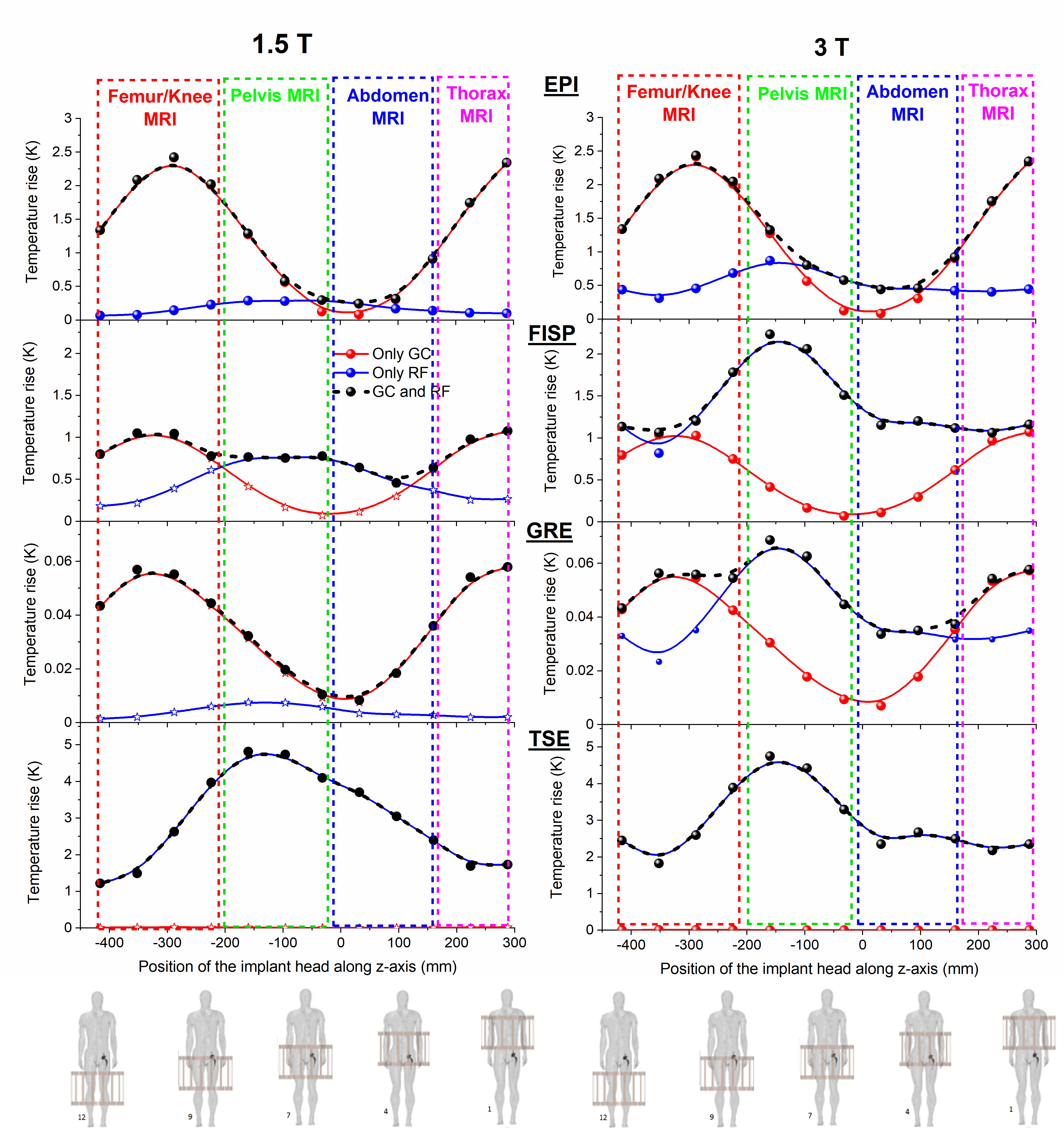
Figure 3 – Maximum temperature increase in the
whole body volume after 360 s exposure versus
the axial position of the hip implant in the coils, corresponding to the twelve
body positions from 1 to 12. Results for EPI, True-FISP, GRE and TSE (with
constant dead time) sequences. Dimensions of the prosthesis: stem length 142 mm;
hemispherical head diameter 30 mm; acetabular shell diameter and thickness 66
mm and 8 mm; screw length 34 mm; polyethylene liner thickness 10 mm.
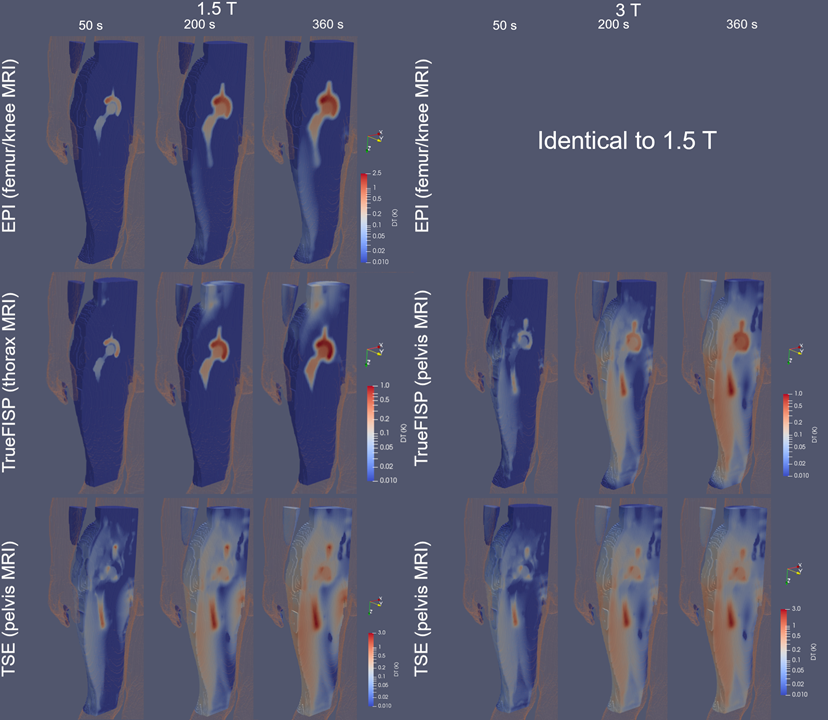
Figure
4 – Time-spatial evolution of the temperature increase around the prosthesis
for three analysed sequences (screenshots after 50 s, 200 s and 360 s). For the 3 T group, the results for the EPI
sequence are not reported, being almost identical to those at 1.5 T. The
results for the TSE sequence refer to a constant dead time of 5.67 s. A region of influence
around the implant was defined as a parallelepiped box of
size 21.7 cm × 18.8 cm × 28.2 cm.