Wonje Lee1, Fraser Robb2, John Pauly3, Shreyas Vasanawala1, and Greig Scott3
1Pediatric Radiology, Stanford University, Palo Alto, CA, United States, 2GE Healthcare, Aurora, OH, United States, 3Electrical Engineering, Stanford University, Palo Alto, CA, United States
1Pediatric Radiology, Stanford University, Palo Alto, CA, United States, 2GE Healthcare, Aurora, OH, United States, 3Electrical Engineering, Stanford University, Palo Alto, CA, United States
The shortest line of sight antenna arrangement within a simulated bore provides the minimum system fidelity degradation for wireless link fidelity
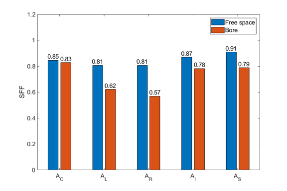
Figure 5. Comparison of calculated SFF numbers
for each Tx – Rx pair
in free space (blue) and within
the bore (red). Note
that SFF = 1 is a perfect reconfiguration, SFF = 0 means no correlation at all. Those within
the bore resulted in lower numbers for all cases, compared to the free
space. The SFF
at the center pair (AC) shows the minimum
difference between free space and the bore, whereas the left and the right
pairs represent a relatively large difference.
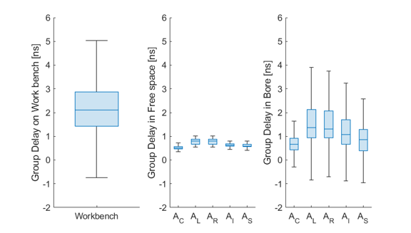
Figure 3.
Calculated group delay distribution in nanoseconds
for each antenna pair on the
workbench, in free space, and within the bore. Group delays within the bore
show higher dispersion for all cases, compared to the free space. These results
are corresponding to the transfer functions
in figure 2, noting that group
delay is the phase gradient over frequency.
