Thomas Dardano1, Rolf Gruetter1,2, and Daniel Wenz2,3
1Laboratory of Functional and Metabolic Imaging (LIFMET), Ecole Polytechnique Federale de Lausanne (EPFL), Lausanne, Switzerland, 2CIBM Center for Biomedical Imaging, Lausanne, Switzerland, 3Animal Imaging and Technology, Ecole Polytechnique Federale de Lausanne (EPFL), Lausanne, Switzerland
1Laboratory of Functional and Metabolic Imaging (LIFMET), Ecole Polytechnique Federale de Lausanne (EPFL), Lausanne, Switzerland, 2CIBM Center for Biomedical Imaging, Lausanne, Switzerland, 3Animal Imaging and Technology, Ecole Polytechnique Federale de Lausanne (EPFL), Lausanne, Switzerland
Dielectrically-shortened dipole antenna can be a
promising alternative to its inductively-shortened counterpart in a loop-dipole
combination for human brain MRI at 7T.

Fig. 3. A) Electromagnetic field simulations: B1+/B1-
field distribution in the spherical phantom as a function of distance (5-mm:
tuned, 20 and 30 mm: detuned). B) Difference maps showing the expected gain in
B1- for the dielectrically-shortened dipole antenna and
its combination with the loop element (especially for the detuned case).
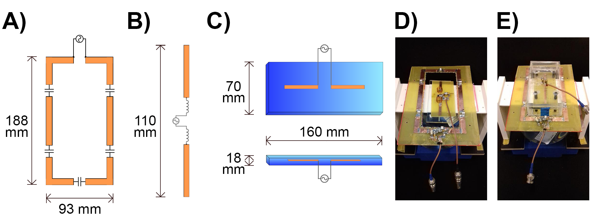
Fig. 1. Simulation view and
photos: A)
Diagram of the loop coil B) Diagram of the inductively-shortened dipole antenna (Ind), C)
Diagram of the dielectrically-shortened dipole antenna (Diel) D) Comb 1 (Loop+Ind) E) Comb
2 (Loop+Diel).