Vincent Hammersen1, Finya Ketelsen1, Andreas Rennings2, and Gregor Schaefers1,3
1MRI-STaR Magnetic Resonance Institute for Safety Technology and Research GmbH, Gelsenkirchen, Germany, 2General and Theoretical Electrical Engineering (ATE), University of Duisburg-Essen, Duisburg, Germany, 3MR:comp GmbH, Gelsenkirchen, Germany
1MRI-STaR Magnetic Resonance Institute for Safety Technology and Research GmbH, Gelsenkirchen, Germany, 2General and Theoretical Electrical Engineering (ATE), University of Duisburg-Essen, Duisburg, Germany, 3MR:comp GmbH, Gelsenkirchen, Germany
This study indicates that inhomogeneous E-field excitement
of test objects even within the ±1dB and ±20° phase shift limits can have a
major impact on the RF-induced heating of implants. Local
field Magnitude und directions should not be disregarded.
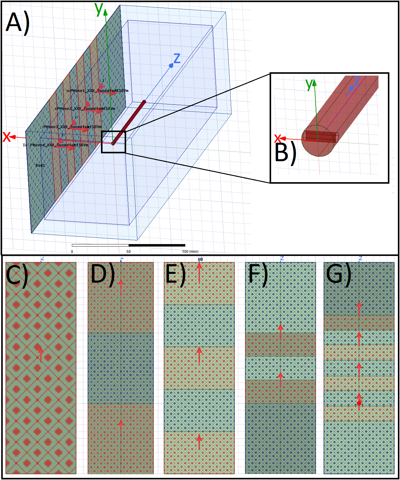
A)
HFSS setup with a central test object and in-phase Plane
Wave excitation (red dotted), separated by radiation boundaries (blue dotted). Remaining
surfaces are terminated by
PML boundaries. Outer Box is the overall
Simulation Box; Inner Box is the VLD export box. B) close up of the titanium
rod tip C) single PW source, D) dual outer PW sources (also used for phase
variations), E) three PW sources, F) two inner PW sources and G) four inner PW
sources. The 300mm central line is identical with the z-axis.
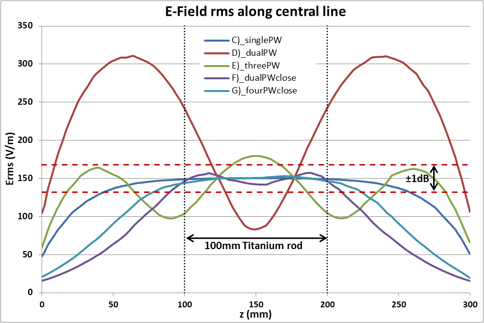
Root
Mean Square of the tuned (150V/m) E-Field Magnitude for the five different
excitation setups along a 300mm central line in the centre of the simulation
volume. The 100mm tuning line, resp. the test object, is situated between 100mm
and 200mm. The dotted red lines indicate the ±1dB (12%)
limitation.